faCADes |
Plugin for AutoCAD & ZWCAD
AutoCAD and ZWCAD model double facades Plugin.
FaCADes is a program to assist with the design, optimisation and drawing of ventilated façades along with their metallic substructure. In collaboration with CD Consultoría.
From €2.800


faCADes’s main functions
Enables simple and quick iterations in the design phase
Supports multiple façades on a single drawing
Bill of materials for both the façade pieces and their metallic substructure
Can be customized to support your own constructive systems
faCADes’s main benefits
Agile budgeting
Resource optimization
Optimization of materials with optimal consumption


Set up your customised plan
Do you need a customised solution?
Count on us for a customised solution that perfectly fits your needs.
How to use faCADes
Other products that work with faCADes
Save more than 90% of the time with faCADes
Unlock a world of efficiency with Camilion and Save time. Click to revolutionize your workflow now!
What is faCADes?
faCADes is a modular program for AutoCAD and ZwCAD designed to simplify the design, optimization, and documentation of ventilated façades and their metal substructure.
Compatibility
- AutoCAD: versions 2018 to 2026
- ZwCAD: versions 2021 to 2026
- Adaptable to other CAD/BIM environments upon request
Available Languages
- Spanish
- English
- Other language on demand
System Architecture
The application is organized into four main modules:
1. Modulation of Ceramic Panels
This first module defines the façade system to be used. It allows the creation of project layers, the main partition lines, and the configuration of façade components.
This step is essential to establish the geometric and construction basis of the system.
2. Metal Substructure
This module focuses on defining the support structure for the ventilated façade. Here the structural system is specified, and the main working lines are generated.
3. Drawing Generation
4. Bills of Materials and Panel Schedules
Each module is based on a predefined system that determines the CAD layers, panel types and sizes, and other construction parameters.
Initial Workspace Configuration
Before starting any project, it is essential to configure the working environment properly.
1. Running the faCADes Module
The first step is to launch the faCADes module, which can be done either directly from the command line or from the Camillion menu.
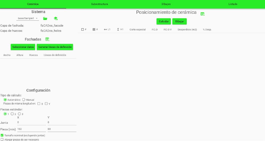
2. Creating Layers According to the Predefined System
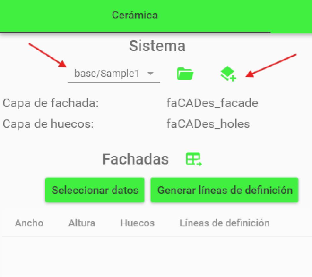
Next, within the Ceramic Module, select the façade system to be used. Once selected, click on the “CreateLayers” button to automatically generate all the layers required for the module to work properly.
The program will generate a complete list of layers, which will be crucial for the next steps.
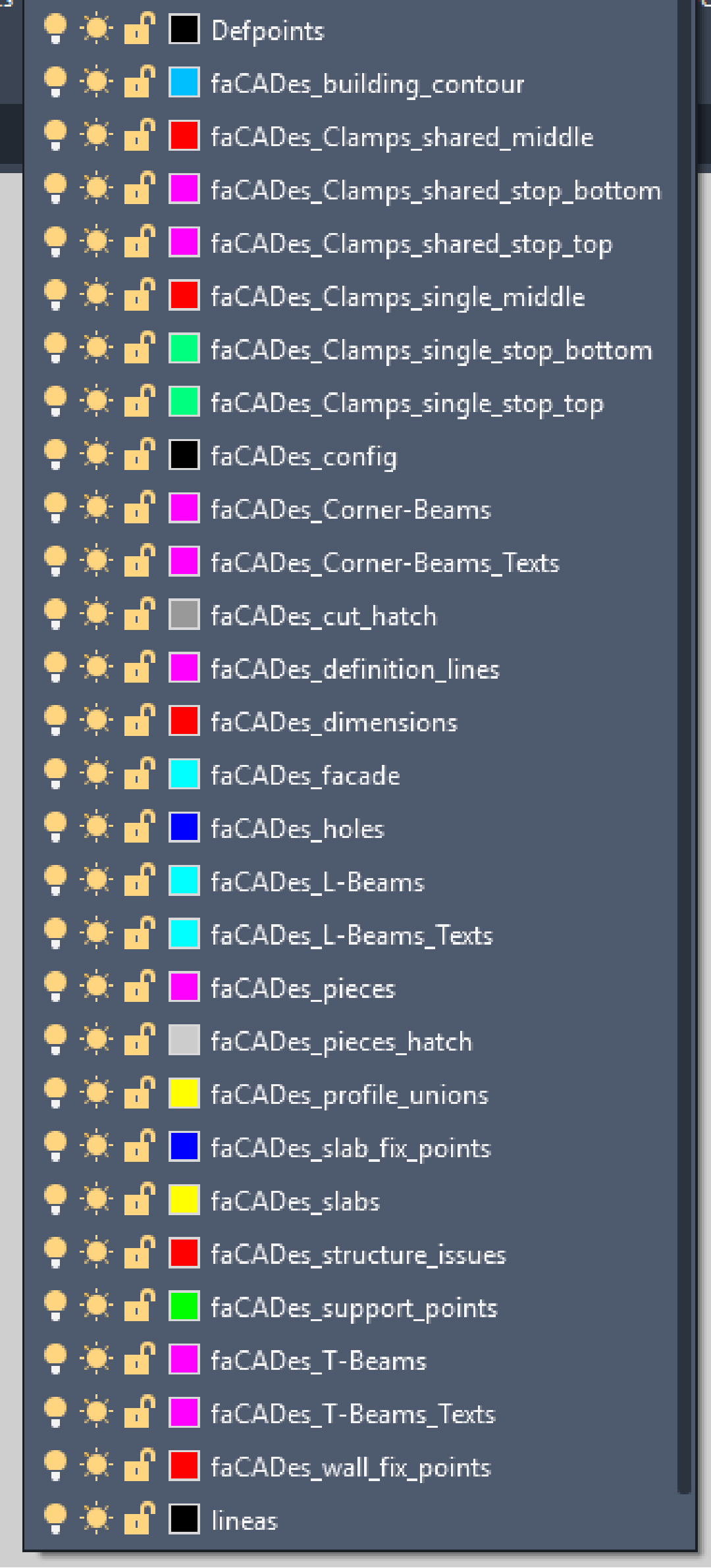
Layers vary depending on the selected façade system.
3. Drawing the Building Outline and Façade Elements
The next step is to draw the building outline and its openings using the layers generated above:
- Draw the building contour polylines on the layer faCADes_building_contour
- Draw the façade contour polylines on the layer faCADes_facade
- Draw the openings with polylines on the layer faCADes_holes
- Mark the floor slabs on the layer faCADes_slabs
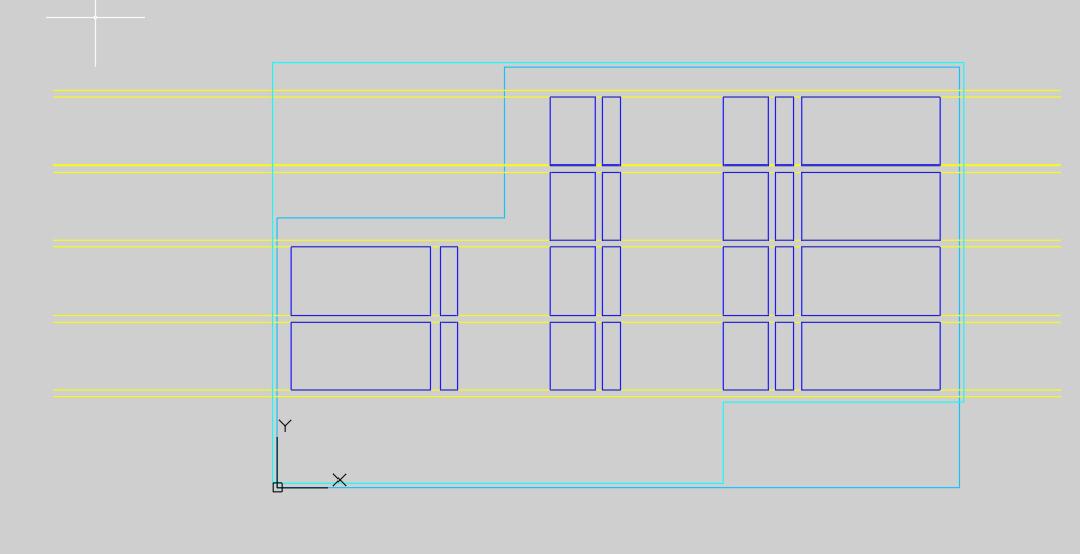
Always use the Polyline tool to define contours.
Work in millimetres and with global coordinates.
Ceramic Module
In this module, the ceramic façade system is defined.
In the System section (on the left panel), select the façade type to automatically generate the layers required for the workflow.
Once the system is selected and the layers generated, go to the Data section (also on the left panel) to assign the layers that define the façade outline, openings, and reference lines required to set up the modulation.
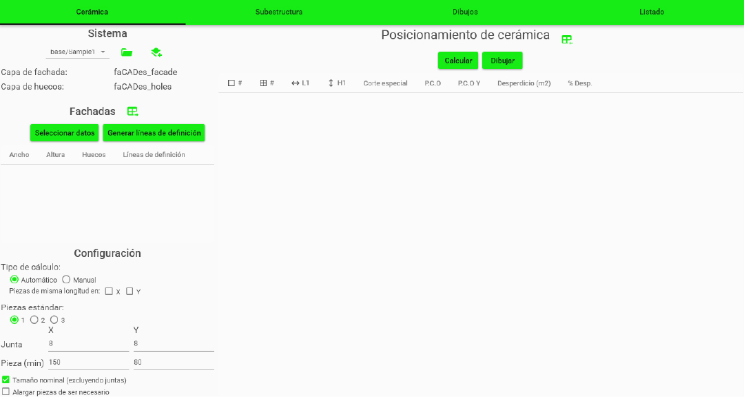
In the Configuration panel (on the left side) you can adjust calculation parameters:
- Modulation method: Automatic or Manual
- Equal pieces along X, Y, or both axes
- Number of piece types (1 to 3)
- Minimum dimensions and joint widths
In the Ceramic Positioning panel (central section), two options are available:
- Calculate: Displays the total number of pieces generated: total pieces before cutting, cut pieces, and waste percentage.
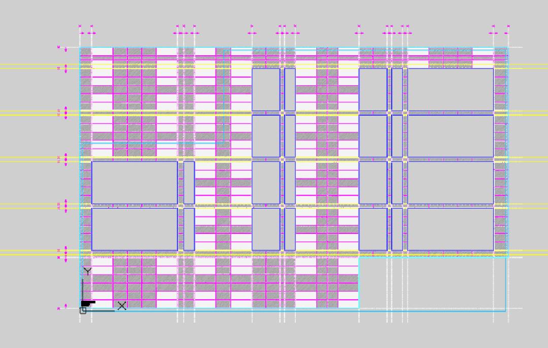
- Draw: Generates the configured panel layout in the model space.
Substructure Module
This module defines the support structure for the ventilated façade.
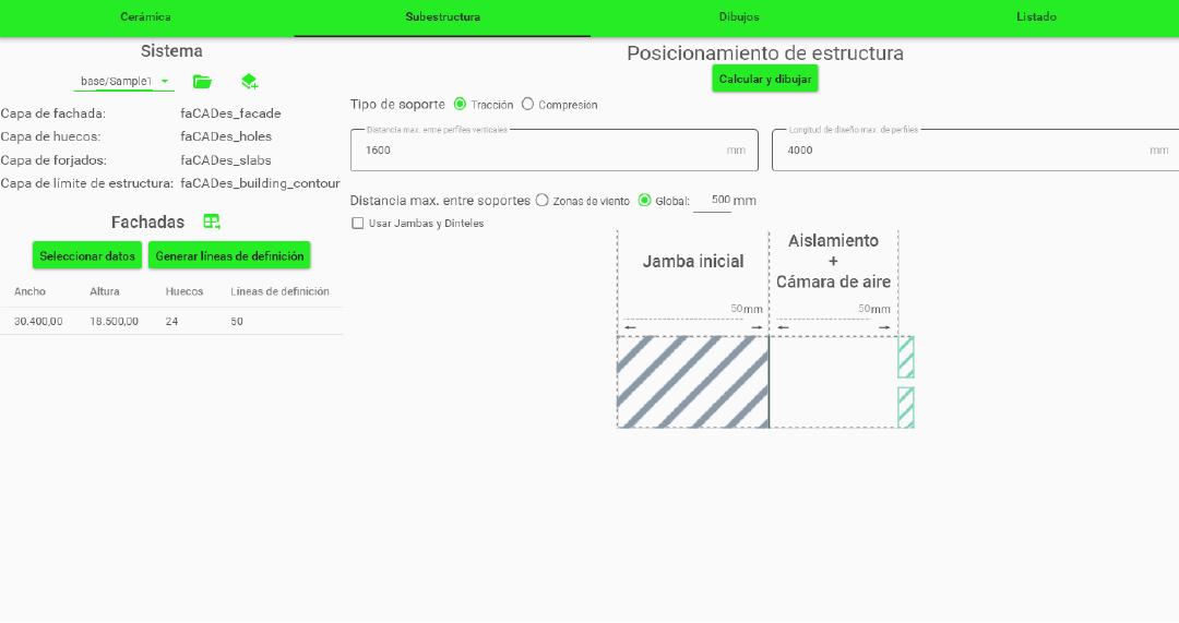
On the left panel, in the System section, you will find the layers involved in the substructure definition. Then, from the Façade section, select the data layers used in the previous phase:
- Building outline
- Openings
- Floor slab lines
- Structure boundary
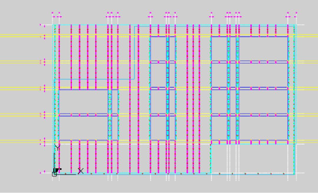
Once the selection is completed, click Calculate and Draw. The program will automatically generate all support structure elements in the main drawing and distribute them across their corresponding layers.
Before running the calculation, you must define the type of support system (tension or compression) and its technical properties, such as maximum anchor spacing or reference structural system.
Drawing Module
In this module, technical drawings for both the ceramic panels and the structure are generated.
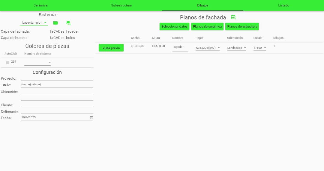
In the left panel (System section), you can select the layers to be included in the drawing.
In the Configuration section, you can add project details such as the project title, client’s location, date, and other identifiers that will appear in the drawing title block.
In the central panel (Façade Drawings), select the elements from the main drawing to include in the final drawing. Next, indicate whether you want to generate Ceramic Drawings or Structure Drawings.
Once the selection is confirmed, the program will automatically insert the chosen drawing in the paper space:
- Ceramic option: generates a drawing with the ceramic cladding layout.
- Structure option: generates a drawing showing the ventilated façade’s substructure.
You can adjust drawing size and scale in the configuration section. The Preview allows you to define the façade name to be represented.
Bills of Materials (BOM) Module
This module enables the automatic generation of bills of materials for ceramic panels, structure, and profile schedules required for project execution.
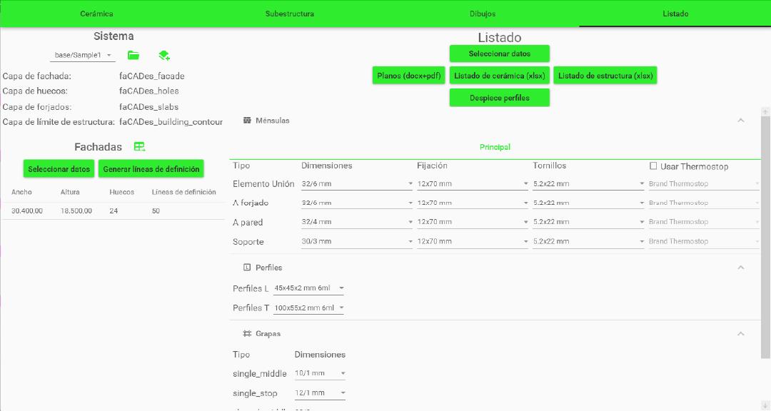
In the System section (left panel), you will find the reference layers used in the model. In the Façades section, select the façade data to be processed. If necessary, you can also generate the definition lines required for accurate modulation.
In the central panel (Select Data), choose all the information contained in the active façade drawing.
After completing the selection, the system can generate:
- Ceramic List: exported to Excel, with a global summary and breakdown by façade.
- Structure List: exported to Excel, with total distribution and breakdown by façade.
- Profile Schedule: includes numbering, coding, and optimization for manufacturing profiles.
Before generating the lists, it is essential to configure the system components in the central panel. This includes a detailed definition of each structural and fixing element:
- Ceramic pieces: type and dimensions according to the system.
- Support elements: fixing systems to slabs and walls.
- Metal profiles: profiles such as L, T, or custom profiles.
- Clips and anchors: type, position, and connection method with the substructure.
This configuration ensures that all generated lists accurately reflect the required materials for the production and assembly of the ventilated façade.
Clicking “Ceramic List” generates an Excel file with the detailed breakdown of all ceramic pieces used in the project.
Clicking “Structure List” generates an Excel file with all the structural components required.
Selecting “Profile Schedule” inserts in the drawing a graphic block with all the profiles used, ready for representation and documentation in the drawings.
Appendix 1: Definition Lines and Modulation
General Notes
- Definition lines have:
orientation (vertical/horizontal),
a position (X for vertical orientation, Y for horizontal orientation),
can be: cutting (without direction) or starting in one direction. - Vertical lines can have LEFT or RIGHT direction.
- Horizontal lines can have UP or DOWN direction.
- To facilitate use and minimize errors in the program, unless the user specifies otherwise, we add:
- Cutting lines at the LEFT , RIGHT , UP ends of the facade.
- A starting line UPWARDS at the bottom end of the facade.
- We generalize by calling FORWARD the RIGHT and UP directions, and BACKWARD the LEFT and DOWN directions.
- We differentiate between:
- modulation length (including joints),
- nominal or piece length (does not include joints).
- There is a setting that indicates whether the measurements provided by the person are for modulation or nominal.
- We always talk about modulation length here.
- Pieces can never be lengthened vertically. Horizontally, it depends on the setting.
- We discuss whether “it can be lengthened,” either by setting, orientation, or because the target length is too much.
Modulation Cases
GO TO (<—)
#  l |  l |  l |  l |d#
#    |    |    |    | #
   Longitud total: L
Starts with: a starting line FORWARD
Ends with: a cutting line or a starting line FORWARD
Place whole pieces (length l) until it’s not possible
Depending on d (the remaining distance):
If it is greater than or equal to the minimum modulation length, add a piece of length d
If it is less than or equal to the minimum modulation length:
And it’s possible to lengthen pieces: the last piece has length l+d
And it’s NOT possible to lengthen pieces: The FORWARD modulation is discarded for an INSIDE OUT modulation
BACKWARD (<—)
Starts with: a cutting line or a starting line BACKWARD
Ends with: a starting line BACKWARD
Always considered equivalent to the FORWARD case.
Before calculating FORWARD , we “rotate” the starting/cutting lines and before returning the modulation, we “rotate” the starting lines again and also rotate the modulated pieces.
INSIDE OUT (<–>)
OPCIÓN 1:
# d/2 |   l  |   l  |  l  | d/2 #
#     |      |      |     |     #

OPCIÓN 2:
# l + d/2 |   l  |   l  |  l  | l + d/2 #
#         |      |      |     |         #

OPCIÓN 3:
# (l+d)/2 |   l  |   l  |  l  | (l+d)/2 #
# | | | | #- Starts with: a cutting line or a starting line BACKWARD
- Ends with: a cutting line or a starting line FORWARD
- Depending on d/2 , half of the remaining distance:
- If it is greater than or equal to the minimum modulation length, add a piece of length d/2 (OPTION 1 )
- If it is less than the minimum modulation length:
- If the piece can be lengthened, add a piece of length l + d/2 (OPTION 2 )
- If the piece cannot be lengthened, add a piece of length (l + d)/2 (OPTION 3 )
- Add whole pieces (length l) until it’s not possible
- The last piece will automatically be symmetrical to the initial piece.
OUTSIDE IN (>–<)
OPCIÓN 1:
#  l  |  l + d  |  l  #
#     |         |     #

OPCIÓN 2:
#  l  | (l+d)/2 | (l+d)/2 |  l  #
#     |         |         |     #

OPCIÓN 3:
#  l  |  l  | d |  l  |  l  #
#     |     | d |     |     #

OPCIÓN 4:
#  l  | l + d/2 | l + d/2 |  l  #
#     |         |         |     #

OPCIÓN 5:
#  l  | (2*l+d)/3 | (2*l+d)/3 | (2*l+d)/3 |  l  #
#  l  | (2*l+d)/3 | (2*l+d)/3 | (2*l+d)/3 |  l  #
#     |           |           |           |     #
- Starts with: a starting line FORWARD
- Ends with: a starting line BACKWARD
- If there is an ODD number of whole pieces:
- And we can extend to l+d , whole pieces are added except for the central piece, which is of length l+d (OPTION 1 ).
- And it cannot be extended to l+d , whole pieces are added except for two central pieces of length (l+d)/2 (OPTION 2 )
- If there is an EVEN number of whole pieces:
- And d is sufficient for a cut piece, whole pieces are added except for the central piece of length d (OPTION 3 )
- And d is too small for a cut piece:
- If we can extend, whole pieces are added except for two central pieces of length l+d/2 (OPTION 4 )
- If we cannot extend, whole pieces are added except for THREE central pieces of length (2*l+d)/3 (OPTION 5 )
Related content
Save more than 90% of the time with faCADes
Unlock a world of efficiency with Camilion and save time. Click to revolutionize your workflow now!
